Home > Calculator Technology > Calculator Electronics
Calculator Electronics
Vacuum
Tubes (Thermionic Valves), Cold-Cathode Switching Tubes & Dekatron Counter Tubes
The early computers of the 1940s and 1950s used the mature vacuum tube (thermionic valve ) technology of the day. In the 1950s and early 1960s transistors were new and undergoing rapid development, and were expensive. So it is no surprise that the first commercially successful electronic desktop calculators, the ANITA Mk VII and ANITA Mk 8 calculators of 1961, made use of tube devices:
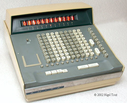
ANITA Mk 8 of 1961, which employs cold-cathode tubes, a Dekatron counter tube, and vacuum tubes (thermionic valves).
1) Vacuum Tubes (Thermionic Valves)
Inside the glass envelope of a vacuum tube (thermionic valve), which is evacuated to a hard vacuum, are several electrodes.
In the the triode, which is the simplest type, is a cathode, an anode, and a grid.
The cathode is heated, which causes a thin cloud of electrons to be emitted from its surface. The nearby anode is given a high positive voltage which attracts these electrons and so a current flows. By varying the voltage on a grid which is between the anode and the cathode, and is in the path of the electrons, the flow of the electrons (ie. the current) can be varied.
The more complicated types such as the tetrode and pentode have extra electrodes to give different control characteristics.
Vacuum tubes were used in the same roles as transistors were later, though the circuit requirements of the two are considerably different.
The ANITA uses a small number of vacuum tubes, several in the power supply and two in the logic circuits
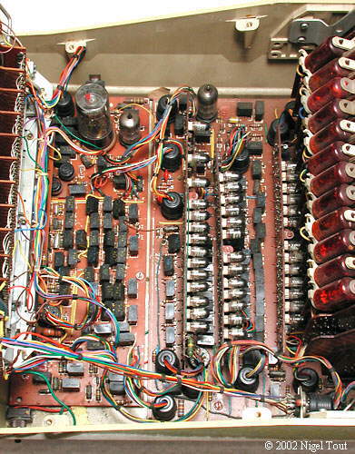

Inside the Anita Mk 8 with the keyboard raised, looking down from the right side showing the keyboard decoding board on the left, which has a Dekatron counter tube at the top, with two vacuum tubes to its right.
The logic boards are right of centre and carry many cold-cathode tubes, while the display boards stand vertically on the far right, each mounting a red-lacquered numerical indicator tube.
As well as these two vacuum tubes there are a further 8 in the rear compartment.
One of the ECC81 double-triode vacuum tubes (thermionic valves), with a 9-pin base.
2) Cold-Cathode Switching Tubes
In contrast to the vacuum tube which has a hard vacuum and a heated cathode, the cold-cathode switching tube has low-pressure gas inside and has an unheated cathode.
The Anita does use a small number of thermionic valves, but the logic circuits incorporate large numbers of Cold Cathode Tubes. In contrast to the thermionic valves the Cold Cathode tubes contain a rarefied inert gas (e.g. neon), and electrons are emitted in an avalanche from the unheated cathode when the voltage between the anode and cathode reaches a high enough value. The flowing current excites the gas inside and produces a glow - this is the way that the small neon mains indicator lamps work. A relatively small voltage on a control grid between the anode and cathode has a great effect on whether a current of electrons flows or not and can switch it on and off.
Cold-cathode trigger tubes operate in a similar way to the modern semiconductor thyristor.
The Anita Mk 8 uses 170 cold-cathode tubes, which were cheap and fairly robust, both electrically and mechanically. An article of 1965 on cold cathode tubes from Mullard Ltd. (a British manufacturer of these devices who also produced a prototype calculator using them) gives an insight into why they were used in these calculators at the time -
"... They are an accountant's dream; a typical modern tube has a life expectancy several thousand times better than the conventional thermionic tube, although they employ voltages of the same order. They are much cheaper than either semiconductor devices or vacuum tubes; they do not require costly materials with a high degree of purity in their manufacture, nor do need transformers or cooling systems to operate. The tubes require no warm-up period and they can take severe overload."

One of the 12 counter/display boards of the Anita Mk 8 with the Nixie-type display tube mounted on the edge. The board holds ten XC-31 cold-cathode switching tubes and 5 black selenium rectifier diode blocks in a ring-counter circuit.
Each switching tube is connected to a number in the display tube, and only one switching tube is turned on at any time. When the board receives a pulse, the next switching tube in the ring counter is turned on and the next number in the display tube is illuminated. If the digit "9" is illuminated and another pulse arrives then the count wraps round the ring so "0" is illuminated and a carry pulse is directed to the adjacent board dealing with the next decade.
The ring-counter circuit can count down as well as up.
Each display board stands vertically and plugs into the main logic board.

A small section of one of the display/counter boards, showing three Hivac XC31 cold-cathode switching tubes and a selenium rectifier.

A view of the logic boards of an Anita Mk 8 during operation. The horizontal main board, underneath, carries three vertical daughter boards. The tubes on the daughter boards are cold-cathode switching tubes and the black blocks are selenium rectifier diodes.
When a cold-cathode tube is switched to the ON state it glows orange like a neon lamp, as can be seen in 5 of the tubes on the daughter boards. When the machine calculates the tubes flicker and a different pattern of illuminated switching tubes results.
Dekatron counter tubes contain ten cathodes in a circular array around the anode. With all the cathodes at the same voltage a glow discharge from one of them to the anode will be transferred clockwise to its neighbouring cathode when a pulse is applied to all ten associated guide (transfer) electrodes. Thus ten pulses to the transfer electrodes will return the glow discharge to its original cathode. These tubes were often used against a mask with the digits 0 to 9 so the glow could be seen through the appropriate number.
In the Anita a type of Dekatron, called a Selector tube rather than a Counter tube, is used whic has individual connections to each of the ten cathodes. This tube is used to provide "scan" pulses to each row of keys in the keyboard so that value of pressed keys can be decoded.


Detail of the keyboard decoder board of an Anita Mk 8 showing the GS10D "Dekatron" decade selector tube, with the small vacuum tube (thermionic valve) to its right, which is part of a blocking oscillator circuit providing driving pulses at a rate of 4000 per second.
The GS10D "Dekatron" decade selector tube. The wires can be seen leading up to the assembly which supports the circular arrangement of electrodes, which is within the dark area near the top.
The 13-pin base fits into a 12-pin socket, and an extra flying lead with a single socket is used which attaches to the anode centre pin.

Looking down on the top of the Dekatron. The red mark is a blob of red paint on the top of the tube.
Note that there is a full circle of electrodes, but the distortion through the glass tube has made those at the bottom of the
photograph disappear.
In the centre is the metal circular disk of the anode. Around it is a circular array of thirty vertical electrodes made up of ten cathodes, which are individually wired, ten "First Guides", all connected together, and ten "Second Guides", all connected together.
When a voltage of 400V to 500V is applied between the anode and one of the cathodes, a discharge starts between them, and alters the potential of the cathode. By applying phased pulses to the guide electrodes the discharge is forced to jump from one cathode to the next, and in the process voltage pulses are produced in sequence at the cathodes, which in the early Anita calculators is used for strobing the keys on the keyboard.

Looking down on the top of the Dekatron during operation. There is a mauve glow around the electrodes as the discharge is passed from one electrode to the next around the assembly.
Note that the glow is brightest at the cathodes, every third electrode, where the discharge sits for the the longest time.
Calculator Technology
Calculator Electronics
Vintage Calculators
Text & photographs copyright, except where stated otherwise, © Nigel Tout 2000-2026.