Home > Calculator Technology > Calculator Electronics
Calculator Electronics
Calculator
Memory Technologies
Modern computers often have hundreds of Megabytes of cheap semiconductor memory. In the 1960s and early 1970s semiconductor memory was prohibitively expensive for use in any quantity in electronic calculators. Instead, other technologies were used, especially in programmable calculators, such as:
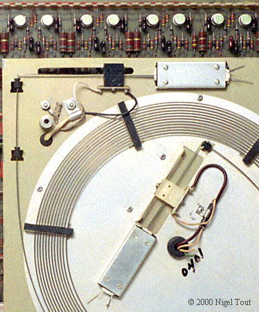
A delay line memory in the Monroe Epic 3000 programmable calculator.
The input and output transducers can be seen, connected to the ends of the coil of wire.
In a delay line memory the 1's and 0's of the binary data are converted to acoustic pulses at one end of a coil of wire. These acoustic pulses travel at the speed of sound in the wire to the other end where they are converted back to an electrical signal and with amplification back into the original binary data. The binary data is effectively "stored" on the wire during the fraction of a second that the pulses take to travel the length of the wire. By continuously feeding the binary data back into the delay line a quantity of data can be stored indefinitely, or can be overwritten by new data.
In practice, delay line memories usually operate in torsion mode rather than compressive mode. That is the electrical signal is converted to twisting pulses which travel the length of the wire, as ilustrated in the diagram and photograph below.
The twisting pulses are produced using tapes of magneto-restrictive material, such as nickel. Two of these have one end welded to the circumference of the wire and the other end clamped in a damping material. Current pulses in coils around the magneto-restrictive tapes produce magnetice fields which cause the tapes to change length. By using pulses of opposite polarity one tape contracts and the other expands, so giving a twisting movement to the end of the delay line.
The torsion pulse travels the length of the delay line where it is converted back to an electrical signal by a transducer with a similar arrangement to the sending end. In this case the magneto-restrictive tapes are stretched and compressed by the torsion pulse, producing a magnetic field around each of them. The magnetic fields in turn produce currents in the coils around the tapes which are converted back to binary data.
Delay line memory is a dynamic memory, that is the data being stored needs regular refreshing, and it is lost when the power is switched off.
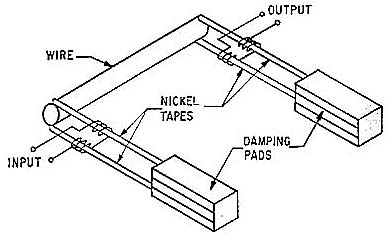
Diagram of torsion mode delay line memory and its input and output transducers.
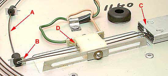
One of the transducers in a torsion mode delay line memory, from a Monroe Epic 3000 programmable calculator.
A) The delay line wire.
B) Magneto-restrictive tapes. One is welded to the top and one to the bottom of the delay line.
C) Clamp which securely holds the ends of the magneto-restrictive tapes. The
pulses in the tapes are damped by a resilient material.
D) Electrical coils around the magneto-restrictive tapes.
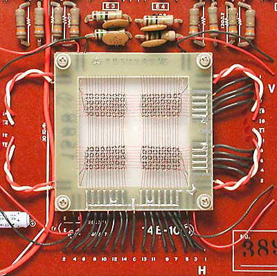
Magnetic core memory inside a Casio AL-1000 programmable calculator, with a capacity of 448 bits.
Magnetic core memories make use of the magnetic properties of tiny ferrite cores, which can be magnetised in either of two directions through the core.
A core memory is made from an array magnetic cores which have vertical and horizontal wires threaded through them, as shown in the photographs. Current pulses through any single wire has a magnitude which is below the threshold to produce a magentic field large enough to flip the magnetisation of a core from one state to the other. However the combined magnetic field if both the horizontal and vertical wires through any core are energised is sufficent to flip the magnetic state of that core. Thus a core can be magentised into two states which can be regarded as logical 0 and 1.
However, it is necessary to sense the direction of the magntic field of any core to determine whether it is storing a 0 or a 1. This is performed using the diagonal sensing wire which threads through the cores. To sense the state of any core the horizontal and vertical wires through that core are pulsed to magnetise that core into one of the states, say 1. If the core was in the other, 0, state then as it changes to the 1 state the sudden change in magnetic field will induce a pulse in the sense wire. If the core was already in the 1 state then it will not change state and there will be no pulse induced in the sense wire. But if there is a pulse in the sense wire then we have just altered the logical state of that core and must appropriately pulse the horizontal and vertical wires through it to return it to its original state.
Magnetic core memory is a static memory, that is the data does not require refreshing. Also the data is retained when the power is switched off, so is potentially available when the power is restored. However, in some machines powering up the electronics produced spurious pulses to the magnetic cores which lost the data they had stored.
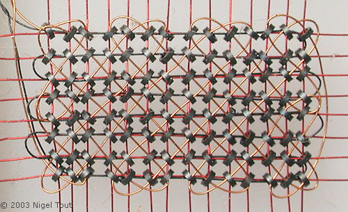
Close up of one section of the magnetic core memory of the Casio Al-1000.
Each core has horizontal and vertical "magnetising" wires and a diagonal "sensing" wire.
Douglas W. Jones, of the University of Iowa Department of Computer Science, has a very interesting description with diagrams of the operation of ferrite magnetic-core storage at "Core Memory: The dominant technology from 1960 to 1980". Here there are also links to examples of core memory used in various machines.
Calculator Technology
Calculator Electronics
Vintage Calculators
Text & photographs copyright, except where stated otherwise, © Nigel Tout 2000-2026.