Calculator Displays
The type of display used in a calculator depended on the technology available at the time, the cost of the display, the power consumption of the display if being used in a portable machine, and the legibility of the display.
A simple time-line for display technology is:
Early 1960s - (1) Cold-cathode numerical display tubes, such as the "Nixie" tube, (2) cathode ray tubes (CRTs), and (3) incandescent filament lamps were the only display technologies available.
About 1967 - (4) Vacuum fluorescent display tubes were pioneered by Sharp.
1971 - (5) Light Emitting Diodes (LEDs) first used in a commercial calculator - the Busicom LE-120 "Handy".
1971 - (6) First-generation Liquid Crystal Displays (LCDs) used in a commercial calculator - Rockwell.
1973 - (7) Second-generation Liquid Crystal Displays (LCDs) introduced.
On this page, click on an item in the list below to go to that section
- 1) Cold-cathode Numerical Display Tubes ("Nixie" tubes).
- 2) Cathode Ray Tube (CRT) Displays.
- 3) Incandescent Lamp Displays.
- 4) Vacuum Fluorescent Displays (VFDs).
- 5) Light Emitting Diode (LED) Displays.
- 6) Liquid Crystal Displays (LCDs).
- 7) The Display War.
- 8) Identifying the display type from its colour.
See also the excellent article by Rick Furr "Electronic Displays - An Overview of Technology" in the Collecting Calculators section of this site.

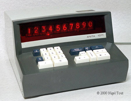
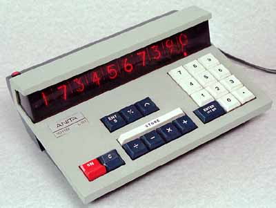
The cold-cathode display tubes of an Anita 1011LSI calculator in use. Note also the small neon lamps used to indicate the decimal point (the third from the right is energised).
Cold-cathode display tubes were developed in the early 1950s and were used in the first electronic desktop calculator, the Anita Mk VII of 1961. Requiring high voltages and having a high power consumption they continued to be used into the early 1970s in AC powered calculators. Their use in battery powered calculators is rare; one example is the Anita 1011B LSI.
The cold-cathode display tube and the neon lamp operate on the same principal.
The simple neon indicator lamp consists of a sealed glass tube with two closely spaced non-heated electrodes, an anode and a cathode. The tube
contains neon gas at very low pressure together with a small percentage of mercury vapour. They are often used in AC power sockets to indicate that a socket is switched on.
The gas in the tube initially acts as an insulator and
as the voltage between the anode and cathode is increased then initially practically no current flows. However, a little of the gas in the tube will be ionised by naturally occurring cosmic rays, radioactivity, or ambient
light, into positive ions and negative electrons. The electric field being applied to the electrodes will cause the positive ions to move towards the cathode and the electrons towards the anode. As the applied voltage
is increased so these will start to move faster and faster, colliding with other gas atoms and ionising them by knocking off electrons.
At the 'striking' or 'ignition' voltage the ions and electrons move with such high speeds
that an avalanche of further ions and electrons is produced by all the collisions. This leads to a high current flow, which is kept in check by an external resistor in series, and an amber glow at the cathode.
The cold-cathode display tube is a neon lamp with multiple cathodes. Each cathode is shaped like one of the digits 1 to 9, and they are mounted in a closely spaced stack.
In front of the stack is the anode, formed from an
open mesh grid visible in the photograph above. When the striking voltage is applied between the anode grid and any of the cathodes a discharge is formed and the gas around the cathode glows. Since the cathode is shaped
like a digit the glow is also in the shape of that digit - see the photographs.
In use it can be seen that the numbers are in a stack since some numbers appear further forward in the tube than other numbers.
The life performance of a numerical display tube depends to a great extent on the length of time the discharge is maintained on a single cathode (ie. number). This is because in any gas-discharge device the cathode is
subjected to constant ion bombardment which removes material from the cathode and deposits it elsewhere in the tube. This 'sputtering' is unavoidable, but is limited by keeping the peak current as low as possible, consistent
with visibility of the display.
If a display tube is kept with one cathode constantly glowing (ie. one number displayed all the time) then material is sputtered from that cathode. This only affects the glow of that cathode
a little, but the sputtered material lands on the other cathodes and affects the current required to make them glow, and can lead to uneven illumination.
If the discharge is cycled between characters regularly, this gives a much
improved life since each cathode, although receiving some sputtered material, is subjected to the cleansing action of bombardment.
Typical figures quoted in published data for the life of a numerical indicator tube is 5,000
hours with a continuous display of one character, and 30,000 hours when sequentially changing from one digit to the next every 100 hours or less.
Cold-cathode numerical display tubes are often called 'Nixie' tubes though this was a trade name of Burroughs Corporation which was an early developer of this technology. Other names used are Pixie tube and Numicator tube.
Around 1970 the Philips company marketed the first generation of its 'Pandicon' display which consists of the 'Nixie' type assemblies of several digits mounted in a single horizontal tube. Calculators with this display include the Data Devices Brock 880/1 and the GENIE 247.
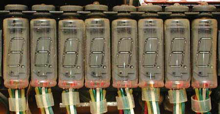
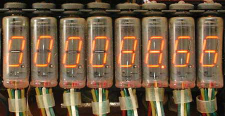
Several Sanyo models of the early 1970s use a type of discharge tube, shown above and below, which at first sight appear to be filament lamps. However the shiny wires are actually electrodes, with the surrounding black metal being the other electrode, arranged as 7-segment displays and decimal point. Each segment operates in the same way as a small neon lamp, so with an applied voltage of about 60v an amber discharge is generated around that energised wire electrode. Shown below is part of a display where segments and a decimal point are energised to display the digits '000088.66'.
The cost of a Burroughs Nixie tube in 1971 was about $2 each for lots of 10,000, which made them very competitive. However their size, high power and voltage requirements were
disadvantages.
Around this time Burroughs introduced the "Panaplex" display providing multiple digits in a single planar tube, see below. Also based on cold-cathode technology, it used the familiar 7-segments to produce
each digit, and required less manual assembly during manufacture and so was cheaper per digit. It also made more efficient use of space so that more digits could be packed into a smaller size. Although more common in
desktop calculators the Panaplex was also used in some hand-held calculators. See the Compucorp 324G and Keystone 88.
Above is a Burroughs 'Panaplex' display in use in a Keystone 88 hand-held calculator of about 1974. The digits are larger than those of LED displays of the time.
The version of the Panaplex II display for hand-held calculators was described in the journal 'Electronics' in March 1972[1]:
"A gas-discharge display
for hand-held calculators that offers large characters in a small, inexpensive package should give light-emmitting-diode displays a run for their money. At least that's what Burroughs Corp. hopes to do with the latest addition to its Panaplex II line, an eight-digit model with each digit measuring 0.2 inch—twice the size of the most popular LED display, says Burroughs' Electronic Components division.
The latest models in the Panaplex II line, which includes panels with 0.25-, 0.4-, and 0.7-in. digits, comes close to the magic dollar-a-digit figure—Burroughs quotes a price of $1.10 per digit in quantities of 50,000 eight-digit monolithic displays.
This eight-digit panel, furthermore, measures 2.65 in. long, 0.69 in. high, and is only 0.197 in. thick—not including the tubulation projecting from the rear, a relic of the process of evacuating the individual digit tubes and filling them with neon gas.
The panel is also quite economical in its power dissipation. It requires only 0.35 to 3.0 milliwatts per segment, depending on the brightness needed, and typically will use less than 1 mw per segment. This corresponds to a maximum of 7 mw per digit or 56 mw for the entire panel, when everything is lighted; but on the average, perhaps no more than five digits of five segments each are on, reducing the average dissipation to 5 mw per digit or 25 mw for the panel. At this rate, four standard carbon-zinc batteries, AA size, would last about 200 hours.
In one test, Burroughs engineers purchased a small calculator and replaced its LED display with the new Panaplex unit. This reduced the calculator's total power requirements for display and computation from 800 mw to 350 mw.
In most hand-held calculators made with metal-oxide-semiconductor circuits, no interface drivers are necessary. Even though the Panaplex II panels are 170-volt gas-discharge devices, their anodes can be driven with voltage swings and current that conventional MOS circuits can provide—sometimes even through passive components instead of transistors.
Panaplex technology is basically the same as that of the old familiar Nixie cold-cathode tubes, differing primarily in their low-cost mode of construction. Their life is expected to be as good—some Nixie tubes are known to have operated continuously for over 120,000 hours, or 14 years. They contain no wire bonds—the interconnections that are most likely to fail first in some LED designs.
Like Nixies, the Panaplex panels emit an orange-red light, which is spread over a relatively broad part of the visible spectrum and is centered near the middle of the perception range of the human eye. Therefore, the panels can be viewed continuously for long periods without discomfort, and are not difficult for color-blind persons to read, as are some bright-red LED displays, which cover a narrow spectral range."
Above is shown the sandwiched glass plates of a Panaplex display. The rear has a sealed glass nipple where the vacuum was achieved during manufacture.
This photograph illustrates that depending
on how the ambient light falls on an unlit Pananplex display it characteristically shows the individual 7 segments of each digit or the cell of each digit.
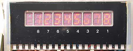
Above is another, less common, amber gas-discharge display showing the digits '12345678'. This example is made by NEC (Nippon Electric Company) and is in a Sanyo ICC-809 hand-held calculator.

A Friden EC-132 calculator showing the Cathode Ray Tube (CRT) display and 4 lines of a calculation.
The cathode ray tube has been in use since the 1920s and was commonly used until recently in televisions, radar displays, and oscilloscopes. Its first use in a desktop calculator was in the Friden EC-130 (early 1964) and EC-132 (with square root).
Although CRTs can display several lines of a calculation they are bulky and have high power requirements, which restricted their use to a few AC powered desktop calculators of the mid to late 1960s.
The four lines on the crt of an EC-132.

The photograph above shows the typical bottle shape of the early instrument type CRT and its metal shielding casing. Anyone who has seen inside a modern television or computer monitor (danger - very high voltages present when in use) will have seen the much fatter, squatter versions which they used.
On the right of the tube is the electron gun, where a heated filament produces a cloud of electrons. These are focused into a beam and accelerated towards the fluorescent display screen on the left by an anode with a high positive voltage. The beam is deflected to write the electron stream on the fluorescent display and so produce the visible numbers.
These CRT display tubes were used in a few calculators of the mid to late 1960s, including Friden EC-130, Friden EC-132, Hewlett Packard HP9100A.
3) Incandescent Filament Lamp Displays
Incandescent filament lamps were employed in two different methods
Method 1 - Seven-segment displays.
Each digit makes use of 7 separate filaments arranged in the familiar pattern so that all numbers 0 to 9 can be displayed. Very few calculators used this type of display which can easily
be confused with the amber-coloured cold cathode numerical display tubes shown above in Section 1.
Method 2 - 'Light-Pipe' Display Modules.
Each digit consists of a stack of clear, flat plastic sheets each with one digit (0 to 9) inscribed. When a sheet is illuminated at its end by a small
filament lamp the light from the lamp is piped along the sheet and is scattered by the engraved number which then can be seen quite brightly.

The 'light-pipe' display modules of a Canon Canola 130S, from about 1968.


Different numbers being displayed by the 'light-pipe' display modules of a Canon Canola 130S.
The photographs below are of a similar, though larger, 'light-pipe' display module to those in the Canon Canola 130S, which are of a more compact design but work in an identical way.


Removing the cover reveals the stack of plastic light-pipe sheets, one for each number 0 to 9 in this module. Decimal points sheets could also be fitted.
Each sheet carries its number marked out in an array of conical
pits in its surface. When a light is shone into the edge of the short side of a sheet the light is piped round the corner, as with fibre optics, and illuminates the pits and so the number is seen.
The bottom of the module can be removed to allow replacement of the tiny filament lamps. There is one lamp to illuminate each 'light-pipe' sheet. This arrangement allows the numbers to be stacked closely together while being illuminated by the relatively bulky filament lamps.
These 'light-pipe' numerical display modules only require the low voltage drive of the filament lamps. But the lamps have the disadvantages of high power consumption (though not much of a problem in an AC-powered calculator), short operating life, and a slow response. They were only used in a handful of AC powered desk calculators in the late 1960s early 1970s.
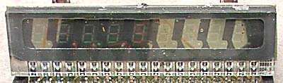
First-generation VFD - A separate tube for each digit
In June 1967 the journal 'Electronics' reported that Japanese calculator manufacturers were battling the high royalties that Burroughs Corporation was asking when they produced copies of its Nixie tubes[2]. This resulted in the first generation of Vacuum Fluorescent Display tubes (VFDs) being developed in Japan jointly by Hayakawa (Sharp) and the Ise Electronics Co. These individual 'Digitron' tubes were used first in the Sharp Compet CS-16A calculator, launched at the end of 1967, and can also be seen in the Sharp QT-8D, Sharp EL-8 and other Sharp calculators manufactured around 1970. The early VFD tubes used in Sharp calculators produce very stylised digits as shown below:

First generation VFD tubes in a Sharp EL-8 calculator. These tubes employ 8-segment digits rather than the now more familiar 7-segment digits.

Here the number '123.4567' is being displayed. Note that the calculator electronics do not implement leading-zero suppression and so the half-height zero is used to make the display more
readable.
'Electronics' journal explained[2]: "For the desk calculator, the digit patterns of the tubes were redesigned for better readability. The
"0", for example, has only half the height of other digits. That way, the string of "0's" before the first significant number in the display is no longer a nuisance and there's no need to blank
them out."
Vacuum Fluorescent displays (VFDs) can be considered to be flattened cathode ray tubes. At the front of the VFD there are one or two fine wires
stretching the height of the tube which form the cathode. The cathodes are heated just to the point where they emit electrons but do not glow.
The digit is formed of conductive segments which act as anodes, and each
anode is coated with fluorescent material.
Applying a suitable voltage between the cathode wires and the appropriate anode segments causes electrons emitted by the cathode wires to be attracted at high speed to those anode
segments. Since the segments have a fluorescent coating those which attract and are struck by the electrons glow brightly. The colour of the glow is typically green or blue, though modern displays for Hi-Fi systems
produce other colours such as white, red, yellow.
Between the anode and cathode is an open grid. Applying a negative voltage to the grid switches the digit off completely.
Typically, each digit is made of seven anodes
arranged in the typical 7-segment pattern so that all numbers 0 to 9 can be generated. However, some early VFD displays have 8-segment digits (as below), with an extra mini-segment to give a better looking '4', which better
resembles that digit in the then competing 'Nixie'-type tubes.

First-generation VFD tubes were soon produced with less stylised digits, as shown above. Note that each of the tubes here has a digit made of 8 fluorescent anodes arranged in the standard 7-segments and an extra short segment so that "4"s look better, together with a decimal point.

A display using first-generation VFD tubes with 8-segment digits, as seen by the mini-segment on the right of the '4'. Though this extra segment might be present in the tubes of a calculator it was often left unused, which has little effect on the readability of the '4' and simplifies the electronics.

The Royal IC-130 desktop calculator is unusual since it has first-generation tubes with 10-segment digits. These extra segments are not used in this calculator to display digits, but could be used to display the '+' sign.

The Royal IC-130 calculator display in use. Note that it still makes use of the half-height '0'.
Second-generation VFD - All digits in a single tube
In the first-generation VFD each digit of the display required a separate display tube—these were used in both AC and battery powered models, with the latter often using small and narrow tubes.
The next development, the second-generation, was to reduce costs and overall size of the display by squeezing all the digits into one long horizontal tube. These tubes were widely used in early hand-held calculators.

A second-generation VFD with all the digits in a single round tube. This display has 7-segment digits.

Another second-generation VFD with all the digits in a single round tube. This display has 8-segment digits with the extra mini-digit for the enhanced '4', though this was not always used.
Third-generation VFD - All digits sealed in a single flat package
The final developments, third- and fourth-generations, were to do away with the bulky tubular envelope and pack everything into a flat package.

A third-generation vacuum fluorescent display with the digit assembly sandwiched between sealed glass plates. A single vertical cathode wire can be seen mounted vertically above each digit. These are also 8-segment digits, capable of displaying a better '4'.
This form of construction was a short-lived type superseded by the pressed glass sealed fourth-generation type.
Fourth-generation VFD - All digits sealed in a single pressed-glass flat package
The fourth-generation VFD has all of the digits sealed in a pressed-glass flat package. This lower-cost method of manufacture produced VFDs which were very widely used in both desktop and hand-held calculators. However, from the mid-1970s VFDs started to be replaced in hand-held calculators by Liquid Crystal Displays (LCDs) which used much less power and so gave greatly extended battery life.

A fourth-generation VFD in a flattened package made by pressing and welding a domed piece of glass over the digits which are supported on a flat piece of glass. A pair of cathode wires can be seen stretching horizontally across all the digits.

Vacuum fluorescent displays have been developed much further as can be seen in the photograph above of the display from a modern hi-fi sound system.
VFDs continue to be used to this day in calculators, video recorders, Hi-Fi systems, and other equipment where the display glows. These displays are quite bright and their power/voltage requirements are moderate so they were used widely both in AC and battery powered calculators, but are now confined almost exclusively to AC calculators.

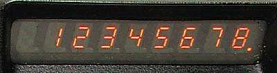
An LED display with its intense red colour.
The LED (Light Emitting Diode) display appeared commercially in the late 1960s. American Calculator Corp., of Dallas, announced the first use of LED displays in a calculator in late 1970. "Electronics" journal stated that it "employs eight Monsanto gallium arsenide phosphide light emmitting diodes in its display". However, in April 1971 it was announced that the company had gone bankrupt, so it may never have sold any commercially. The first calculator with LED display to be successfully marketed was the small Busicom LE-120 "Handy" in early 1971.
Being based on semiconductor materials, the LED display is very compatible with calculator integrated circuits and has a moderately low power consumption.
The initial problems were high cost and the small size of the
characters. With large scale production the price rapidly reduced. The small character size was alleviated by placing moulded plastic magnifying lenses in front, as can be seen below, however this gives a narrow viewing
angle. Due to the small size of LED displays they were very rarely used in desktop calculators of the 1970s.
The LED eventually lost out to the Liquid Crystal Display (LCD, see below) which has a much lower power consumption (it is passive and does not emit light) and has a larger size at little extra cost.
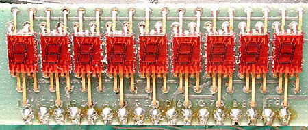
Early 8-digit LED display in a Commodore Minuteman 2 using individual 7-segment array modules. The ninth module on the far left provides "-" sign and overflow indication.

Early 8-digit LED display. This has nine bare 7-segment array LED chip dice mounted on two carriers, and does not use magnifying lenses. The die on the far left provides "-" sign and overflow indication.

LED module showing the typical plastic moulding with magnifying lenses.

LED module showing the 7-segment LED arrays viewed through the magnifying lenses.

LED module showing the number 12345678 being displayed. The array on the left is used for displaying the minus sign and other characters, such as to indicate overflow.
Liquid Crystal Displays (LCDs) were developed in the late 1960s and early 1970s. Thomson-CSF of France was one company involved in their development and demonstrated a calculator with a 16-digit LCD in early 1971 (photograph in "Electronics", May 24 1971). However, they were selling the display at a price of $10 per digit at that time so it would have been expensive and was probably not sold commercially. Busicom announced a LCD version of the LE-120 (itself the first successful LED calculator) in 1971, but it too appears to have never been sold commercially.
First-generation LCD - Dynamic Scattering Mode (DSM) LCD
The first successful use of LCD displays in calculators were in models made by Rockwell for Lloyds (Accumatic 100), Rapid Data (Rapidman 1208LC), and Sears in 1972. These use DSM (Dynamic Scattering Mode) LCDs where the liquid crystal is normally clear but turns opaque white when a voltage is applied. The displays of these calculators require built in side lighting, so removing much of the advantage of low power consumption of the LCD.

First Generation Dynamic Scattering Mode LCD with white or silvery digits against a dark background.
Sharp and COS technolgy
Sharp Corporation were also pioneers in calculators using DSM LCD displays, and in 1973 introduced their 'COS' (Crystal On Substrate or Calculator On Substrate) technology in the Sharp EL-805.
The true COS calculator has a circuit board which is made of a glass-like ceramic, as shown on the left, viewed from the rear of the calculator. The LCD display is formed directly on this circuit board, which also carries at least two layers of conductive tracks and the electronic components. The user actually looks through the circuit board when viewing the display.

The COS technology circuit board of a Sharp EL-805 calculator.
The main board is made of a glass ceramic with the DSM LCD formed under another sheet of glass. The glass circuit board is noteworthy in that there are no holes in it for mounting components; they are all surface-mounted. Conductors are printed on both sides of the circuit board and are covered with a white layer. Connections between the conductors on both side of the circuit board are made by the connector at lower right and the small conventional circuit board attached at lower left.
The use of the glass-like ceramic circuit board was a dead-end in the development of calculators and the COS technology was only used in a small number of Sharp calculator models of the mid-1970s. Subsequent models from Sharp with LCD displays have conventional circuit boards, though the LCD display modules have a similar construction to the display section on the glass circuit boards.
LCDs have the great advantage of very low power consumption since they are passive displays, altering the reflection of ambient light rather than actively generating light. However, a DSM LCD does require a small current to flow through a display segment when it is turned on. Although this current is much smaller than that of a LED or VFD display, it is significantly higher than the current to drive the Twisted Nematic (TN) display, below, which is a field-effect device.
When LCDs were first introduced in calculators there was a lot of discussion about the stability of the early liquid crystal material. This may be justified since calculators with DSM LCDs often have defective displays, though often the defect appears to caused by the display elements leaking rather than the liquid crystal ageing. Storage away from high temperatures is recommended.
Second-generation LCD - Twisted Nematic (TN) LCD with yellow filter
In 1975 an improved type of LCD was introduced in calculators which did not require any special illumination. This was the Twisted Nematic (TN) type in the Casio pocket-LC. Here the liquid crystal assembly is held between crossed polarising filters. With no voltage applied the liquid crystal rotates the polarisation of light so that it passes through the filters and shows the reflective surface behind. When an appropriate voltage is applied the liquid crystal stops rotating the plane of polarisation of the light and that region appears black. Since the TN LCD is a field-effect device the current consumption is extremely small, which is highly desirable for a battery-powered calculator.
Calculators with early TN LCDs usually have a yellow filter in front to remove Ultra Violet (UV) rays from the ambient light which might damage the liquid crystal.

Second-generation LCD. An example of a TN LCD with black digits and a yellow background - the yellow is actually a filter in front of the display to absorb damaging Ultra Violet light and prolong the life of the liquid crystal material.
Third-generation LCD - Twisted Nematic (TN) LCD without filter
During the late 1970s advances in the liquid crystal material greatly improved its stability, removing the need for the yellow, ultra-violet absorbing filter. These third generation LCDs are used for the displays of modern hand-held calculators and in conjunction with modern integrated circuit techniques result in calculators running for years on one button cell or just on solar power.

Third-generation LCD. An example of a TN LCD without yellow filter and showing black digits on a grey background.
Excellent Youtube videos produced by Michiel de Boer that graphically explain these Liquid Crystal Displays are:
- "The DSM LCD (like) you've never seen" - https://www.youtube.com/watch?v=eGQQWIbD-nM
- "LCD Explained (and more)" - https://www.youtube.com/watch?v=J6W1jYoa1HM
During the late 1960s and 1970s there was much discussion about the best type of display for calculators, especially as new technologies were introduced and the resulting economies of scale led to price competition.
The display technology used in the 1960s was overwhelmingly the cold-cathode discharge numeric display tube, typified by the Burroughs "Nixie" tube, with its amber colour. By 1971 tubes of this type could be bought in quantity for US$1-to-$2-per-digit[3].
A few calculators, mostly from Friden, used cathode ray tubes (CRTs) which could economically give several lines of digits.
However, around 1967 Japanese calculator manufacturers were in dispute with Burroughs Corp., the patent holders of the Nixie tube technology, over the amount of royalties to be paid for using the tubes[2]. Burroughs wanted a royalty of about 45 cents a tube, whereas the Japanese manufacturers wanted to pay no more than about 16 cents per tube. This led to the development in the late 1960s jointly by Hayakawa (Sharp) and the Ise Electronics Co in Japan of vacuum fluorescent displays (VFDs), with a green/blue colour. Having a reduced power/voltage requirement and a bright display these took over from the cold-cathode, "nixie"-type, tubes, especially among Japanese manufacturers, in the 1970s. Displays of this type were also widely used in hand-held calculators till the late 1970s, and they remain the only light-emitting displays still used, in some AC powered desktop calculators.
Light emitting diode (LED)
displays were introduced commercially in 1967, but were initially very expensive, costing about US$60 a digit. By 1971, in quantities of 1,000, 1/8 inch high LED displays could be bought for US$3.95 each[3].
Although more expensive than the numeric display tube the LED had the advantages of small size, low voltage, and lower power consumption, which made it very suitable for the newly
appearing miniature pocket calculators. Although expensive at first, the price of LEDs soon dropped as production quantities increased and competitors entered the market. Within a year or two of their introduction in
calculators in 1971 they were used extensively in hand-held calculators until the late 1970s when they were largely replaced by liquid crystal displays (LCDs).
All of the light emitting displays have the disadvantage that they are difficult to read in bright ambient light. They must also use energy to generate light, but power consumption could often be reduced by pulsing them, which could give the same apparent brightness at a lower average current.
The liquid crystal display (LCD), also introduced in calculators in 1971, required a less technical production environment and cheaper materials than the LED, and so could be made much cheaper. It also had tiny power requirements, and being reflective was easily readable at all normal office lighting levels and in full sunlight. However, early manufacturing problems, the slow response speed of early liquid crystals, and concerns about the life and temperature stability of the liquid crystal material held up its wide acceptance till the mid 1970s with the introduction of the TN (Twisted Nematic) type. Then there was no stopping the LCD and by 1978/9 it dominated the hand-held calculator market and allowed credit card-sized calculators to be produced.
A) If the digits glow -
- Intense red -> Light Emitting Diodes (LED).
- Delicate Amber -> Cold-cathode Gas Discharge (eg. 'Nixie', 'Panaplex', etc).
- White -> Filament lamp/Light-Pipe.
- Bright green -> Vacuum Fluorescent (VFD).
- Bright blue -> Vacuum Fluorescent (VFD).
There is no known calculator before 1980 with a green LED display - green LEDs were developed after the red variety and were more expensive.
LED displays were very rarely used in desktop calculators.
B) If the digits do not glow then the calculator has a Liquid Crystal Display (LCD).
See also the excellent article by Rick Furr "Electronic Displays - An Overview of Technology" in the Collecting Calculators section of this site.
References:
Calculator Technology
Vintage Calculators
Text & photographs copyright, except where stated otherwise, © Nigel Tout 2000-2026.