
Electronic Calculator Displays
An Overview of Technology
© 1997 by Rick Furr
(email: rfurr@vt.edu)
Reprinted from the Spring 1997 issue of The International Calculator Collector.
One of the more interesting things about old calculators is how they displayed their numbers. As easy as it seems today, in the late 60s and early 70s it was quite hard to devise a display system for a calculator, especially a portable one. This article will describe the construction and operation of the major types of electronic displays both past and present.
CATHODE RAY TUBE

The Cathode Ray Tube (CRT) was developed for television in the 40s. The CRT shoots a focused electron beam from the back of the tube to the front of the tube. The front of the tube is coated with phosphors that glow when they are struck by the electron beam. An image is created by moving the electron beam back and forth across the back of the screen. The beam moves in a pattern from left to right, top to bottom and then it repeats. Each time the beam makes a pass across the screen, it lights up phosphor dots on the inside of the glass tube, thereby illuminating the active portions of the screen. The intensity of the beam is modulated thus causing the screen phosphors to glow with different intensities or to even not glow at all. The desired images to be displayed are actually retraced between 30 to 70 times each second. This keeps the images continually refreshed in the glowing screen phosphors without a flicker being perceivable to the eye.
The electron beam is generated from a filament and electrically charged cathode in the back neck of the CRT. The electron beam is first passed through a control grid. The control grid modulates the intensity of the electron beam. The higher the intensity the brighter the phosphor dot it strikes will glow. Next the beam passes through an accelerating electrode, this will speed up the electron beam. Then the beam passes through a focusing anode. This will focus or tighten the stream of electrons. All of these elements comprise the electron gun structure housed in the neck of the CRT.
The structure on the neck of the CRT is the yoke. The yoke contains four electromagnets placed around the neck of the CRT in 90 degree increments. By varying the voltage of these four electromagnets, the electron beam can be deflected or bent to reach any location on the phosphor coated screen. A final stage of acceleration is achieved with the high voltage anode. The familiar suction cup wire that attaches to the side of the CRT is connected to this anode. This anode is often a metalized surface on the inside of the picture tube. Many thousands of volts are applied to the anode to pull the electrons towards the phosphor coated screen. Phosphors can be formulated to emit many colors though white and green are the most popular for monochrome screens. Additional circuitry in the calculator can create numbers, letters, and other symbols by using the control grid to turn the electron beam on and off, while simultaneously using the electromagnets to deflect the beam to the desired locations on the screen. Many early desktop calculators like the Friden EC-130 and the Hewlett Packard 9100A used CRTs.
NIXIE TUBE DISPLAY

In a Nixie Tube display each numeral is a complete, lighted cathode in the shape of the numeral. The cathodes are stacked so that different numerals appear at different depths, unlike a planar display in which all numerals are on the same plane relative to the viewer. The anode is a transparent metal mesh wrapped around the front of the display. The tube is filled with the inert gas neon with a small amount of mercury. When an electric potential of 180 to 200 volts DC is applied between the anode and any cathode, the gas near the cathode breaks down and glows. The digits glow with a orange-red color.
The name Nixie came about accidentally. A [Burroughs] draftsman making drawings of the device labeled it NIX I, for Numeric Indicator eXperimental No. 1. His colleagues began referring to it as "Nixie," and the name stuck ( Scientific American, June '73, pp. 66).
Interestingly enough the Nixie design is considered "failsafe". If a filament (cathode) fails, the numeral is not illuminated. Whereas, in a seven-segment display if one segment fails, a number other than the intended number may be displayed. The Casio 121-A and the Sharp QT8-B used Nixie tubes.
INCANDESCENT FILAMENT DISPLAY

An Incandescent Filament display is usually housed in a vacuum tube like the either the Nixie tube or the early Vacuum Fluorescent tubes. This display is typically a seven segment style of display where each display segment is formed with a conductive anode tungsten filament. A small voltage placed across a filament will cause it to heat to incandescence. They emit a yellowish -white light that can be filtered to any desired color. The filament voltage (3-5vdc) can also be varied to change the brightness level of the display. The biggest problem with Incandescent displays is they have a slow response time and they consume a large amount of current. A popular version of this type of display was the RCA Numitron. Some early electronic kits used the Incandescent Filament display.
GAS DISCHARGE or PLASMA DISPLAY

A Planar Gas Discharge or Plasma Display Panels (PDP) display utilizes the same principle the Nixie tube does. It's construction consists of sandwiching a hollow center layer filled with neon and a small amount of mercury between a glass front and a ceramic back. A thick conductive paint forms the Cathodes on the inside of the ceramic back. The Cathodes form the segments of each digit. Each digit is covered by a separate Anode that is deposited on the inside of the glass front. The Anodes are formed from a thin transparent layer of tin oxide. When a sufficient voltage is applied between a cathode segment and it's anode, the gas around the cathode segment breaks down and begins to glow. Like the Nixie tube, the digits glow with a orange-red color. Voltage requirements for these displays are typically 180-200 volts DC).
Burroughs manufactured a common brand of PDPs called Panaplex II. PDPs were used in many early calculators including CompuCorp's Scientist series.
VACUUM FLUORESCENT DISPLAY MODULE

The Vacuum Fluorescent display (VFD) consists of a vacuum tube in which there are three basic types of electrodes, the filament (cathode), the anode (segment), and the grid. The VFD is essentially a small Cathode Ray Tube. The filament (or filaments) is a very fine wire that is heated to a temperature just below incandescence. At that temperature it remains virtually invisible but it emits electrons. A transparent metal mesh grid covers each digit and controls the electrons emitted from the filament toward that digit. Seven phosphor coated anodes, arranged in the seven-segment configuration (that form a square eight), glow when struck by the electrons. When a positive voltage of 12 to 25 volts is applied to the grid and the anodes, the electrons emitted by the cathode filament are accelerated and attracted to the positive anode segments which in-turn glow. If the grid has a negative potential then it will block the electrons from passing regardless of the potential of the anodes under the grid.
VACUUM FLUORESCENT DISPLAY TUBE

VFDs were developed in Japan in 1967. Early versions of VFDs were individual digits housed in vacuum tubes like the Nixie tube and Incandescent Filament displays. VFD Phosphors can be formulated to emit red, yellow, and green as well as the more common blue-green color. Later versions would house all of the digits (and other graphics and indicators) in one large glass assembly. Currently VCRs account for 30% of the VFD market and Audio/Video products account for another 30%. Many early series of calculators like the Commodore 412F, Brother 310, and the MITS 816 used the individual digit VFD tubes. Later manufacturers such as TI and Rockwell used the integrated multidigit VFDs in both handhelds and desktops.
ELECTROLUMINESCENT DISPLAY

Thin-film Electroluminescent Displays (ELDs) use a thin film of phosphor (zinc sulfide (ZnS); ZnSe; ZnSMn or other fluorescent materials) sandwiched between a dielectric layer that is sandwiched between two glass plates. Transparent electrodes (tin-oxide) are deposited on the insides of the glass plates. When a sufficient AC voltage (>100 volts) is applied to any of these electrodes the phosphors will be excited and will emit light. ELD phosphors can be mixed with pigments to emit many colors of light including green, blue-green, lemon-yellow, orange, red as well as white light.
This type of solid state display can endure extreme conditions with exceptional tolerance to shock, vibration, temperature, and humidity, while response times remain less than one millisecond. I have not seen ELDs used in calculators but they are used in some laptops, office machines and in the cockpit of the Spaceshuttle. They are also used to backlight LCD panels.
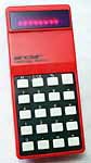
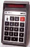
LED DISPLAYS

A Light Emitting Diode (LED) is an special type of diode that emits light when electricity applied to it's anode and cathode. A typical LED requires about 1 1/2 volts DC at 10 milliamps to begin emitting light. LEDs usually produce red light but yellow, green and blue versions are also now available. The LED was first marketed by Texas Instruments around 1962. LED displays (7 or more individual LEDs) were introduced around 1967 but were very expensive. Calculators used LEDs that were arranged to form either a seven-segment display or a dot-matrix display.

Early seven segment displays formed each segment with many LEDs, later seven-segment displays would use one LED per segment with a light pipe to spread it's light across the segment. Also early LED displays were made small in order to keep power consumption down. A clear plastic bubble lens was fabricated into the package to magnify the display for easier viewing.
NUMERIC REPRESENTATION

The dot-matrix style of display would form characters shaped similarly to that of a dot-matrix printer. A dot matrix of 4x7 or 5x7 is typically used. Notice how the 4x7 matrix makes up for the missing 5th column by slightly slanting the columns. LEDs require much more power than LCDs and are more expensive to manufacture. This is the simple reason for their demise from being used in calculators.
LIQUID CRYSTAL DISPLAY

The Liquid Crystal Display (LCD) was first developed at RCA around 1971. LCDs are optically passive displays (they do not produce light). As a result, LCDs require all most no power to operate. Many LCD calculators can operate from the power of a solar cell, others can operate for years from small button cell batteries. LCDs work from the ability of liquid crystals (LC) to rotate polarized light relative to a pair of crossed polarizers laminated to the outside of the display. There are two main types of LCD displays used for calculators today: Twisted nematic (TN) and supertwisted nematic (STN). TN displays twist polarized light to 90 degrees and have a limited viewing angle. STN displays were developed to twist polarized light between 180 to 260 degrees resulting in better contrast and a wider viewing angle.
A LCD consists of two plates of glass, sealed around the perimeter, with a layer of liquid crystal fluid between them. Transparent, conductive electrodes are deposited on the inner surfaces of the glass plates. The electrodes define the segments, pixels, or special symbols of the display. Next a thin polymer layer is applied on top of the electrodes. The polymer is etched with channels in order to align the twist orientation of the LC's helix shaped molecules. Finally, polarizing films are laminated to the outer surfaces of the glass plates at 90 degree angles. Normally, two polarizing films at 90 degrees should be dark, preventing any transmission of light but due to the ability of LC to rotate polarized light the display appears clear. When AC voltage is passed through the LC, the crystals within this field align so that the polarized light is not twisted. This allows the light to be blocked by the crossed polarizers thus making the activated segment or symbol to appear dark.
Many other types of LCD displays are being developed for the laptop and CRT replacement market including full color versions. These include double and triple twisted nematic (DSTN and TSTN) displays and the Active-matrix Thin-film Twisted Nematic and Metal-Insulated-Metal Twisted Nematic (TFT-TN and MIM-TN) displays. Unfortunately these advanced display are too expensive for most of the calculator market. TN LCDs almost completely dominate todays calculator market due to their extremely low power requirements, thin size, and low cost.

References:
Alan Sobel, "Electronic Numbers", Scientific American, pp. 64-73, June 1973.
"Note on the Liquid Crystal Display Industry, https://web.archive.org/web/20160418181108/http://www.auburn.edu/~boultwr/lcdnote.pdf (archive link).
"Display Technologies in Japan", http://www.wtec.org/loyola/dsply_jp/toc.htm.
"Sharp - World of LCDs", https://web.archive.org/web/20000511090945/http://www.sharp-world.com/sc/library/lcd_e/indexe.htm (archive link).
Calculator Articles
Vintage Calculators
Text & photographs copyright, except where stated otherwise, © Nigel Tout 2000-2026.