
Build Your Own
Retro Calculator
Would you like to own a retro LED calculator which you have built from a kit?
Paul Scmidt was taken with the readily available calculator kit from Spikenzielabs, and here shows the stages in its construction. He also passes on valuable tips to achieve the best results.
© 2015 Paul Schmidt
This is a new article which was not originally in "The International Calculator Collector".
Introduction
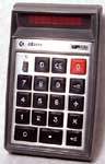
Calculator kits were readily available in the first half of the 1970s from several companies, most notably Heathkit and Sinclair. This was at a time when many calculators were manufactured in the U.S.A. and U.K. where labour costs were high and so there could be some cost saving in buying a kit of parts and assembling it yourself.

A Sinclair Cambridge calculator kit from the 1970s.
With the great transfer of calculator manufacture to Asia, where the labour costs were lower, calculator kits practically disappeared from the market from the late 1970s.
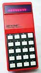
However, with the rise of interest in early electronics there is now an enthusiasm to own modern items that have a retro look. Such is the basic 4-function calculator with LED display and clear casing (showing the components inside) from Spikenzielabs.
Paul Scmidt assembled a Spikenzielabs calculator kit and passes on his experiences with it:
Building the Spikenzielabs calculator kit
I bought a Christmas gift in the form of a snazzy calculator kit. Looking at the kit, I liked it so much that I bought another for myself and put it together last week. It is a basic 4-function machine with floating point, but limited number size (max 6 digits positive, 5 digits negative, all numbers rounded to four decimal places - that is digits to the right of the decimal point – six decimal places may be entered but they are automatically rounded to four decimal places – and gives an error if either number of a calculation is zero, e.g. 5 + 0 = error.
Great clicky tactile keyboard action, brilliant large red LED display, beautiful laser-cut clear case.
Very few electronic components; the main Arduino-programmed microcontroller IC, two capacitors (for internal clock?) and six resistors that are for the keyboard-display-shared matrix scan lines (but resistors only used for the keyboard…they are not current limits for the display).
Powered from one watch battery, powers down after 10 seconds of non-use to save the battery.
The other unique thing about this calculator (the manufacturer claims that they are the only ones doing this) is the laser cut keys. Each key is comprised of two pieces; a clear plastic piece that fits between the actual PCB key switch and the key button, riding within a chamber formed by cutouts in the layers of clear plastic that comprise the case, and the black plastic key itself. The clear part and the black part are bonded together with instant adhesive. The unique part is that the black key starts out as a piece of shiny-finish acrylic plastic, with a protective film on one side. A laser cuts or vaporizes the unwanted film, leaving only the part that protects the desired image on the key surface (like etch resist on a PCB). Then the laser scans the top of the key to cause a roughed up matte surface, except where the protective film remains. Peel off the film and you get a cool looking black key with high contrast between glossy and matte regions.

The box with the calculator kit.

The components of the kit removed from their bags.

Atmel 8-bit micro-controller with in-system programmable Flash program memory. For protection from damage due to any electro-static discharge during handling, the pins of the integrated circuit are inserted in anti-static foam.

The circuit board with the components soldered in place.
From the top: battery holder, LED display, integrated circuit, resistors & capacitors, keyboard switches.

Checking to see if the display visibility could be improved by using a red filter (not supplied with the kit) over the LED modules.

It was decided that the display was improved with a red filter, and so this was super-glued to the LED modules.

Peeling the protective film from the front of a keyboard button. It was found that it was very easy to damage the surface using a sharp, hard tool and so this operation was largely performed using a thumb nail.

The buttons after removing the protective films.

The keyboard buttons have a separate clear bottom part. The top part of each button was accurately attached to its bottom part using casing sections as an alignment jig.

Side view after assembly was completed.

A final test after assembly by performing a simple calculation and pressing the '=' button.
The major challenges of building this kit:
- There are lots of plastic pieces, each with protective film on both sides that laboriously needs to be peeled off. As almost any tool used for this will scratch the plastic in the process, I used my thumb nail, and nearly lifted it off the quick in the course of doing so many!
- The key tops and the clear key bottoms need to be carefully aligned in order to move freely without binding. The kit uses a novel method of temporarily assembling some case sections in the wrong layer-order, to form an alignment jig to help in key assembly and bonding, but great care still needs to be used here.
- The PCB pads are often very tiny, making good soldering skills necessary.
- The LED display has a separate 'chip' for each digit, and in order to fit the PCB and also the precise cutout in the case front, each digit's chip needs to be carefully checked for any excess epoxy that might remain on the sides after manufacturing. If any remains, the display chips will be too large and will not fit. This requires careful scraping with a utility knife, all the while avoiding a slip that will mar the display or cut the fingers.
- The kit was obviously designed to have a red filter in front of the LEDs (each LED digit is raised off the PCB by a laser-cut precision spacer, to get the face of the LEDs flush with the face of the case), but in reality they fall exactly 20mil [thousands of an inch] short of being flush. 20mil is the standard thickness of most red Lexan filters used for LED displays in industrial applications, so I am pretty sure that the designers envisioned use of such a filter, bonded to the face of the LEDs and as a result being itself flush with the front of the case. But no filter was included, nor mentioned in the parts list. Checking around, I found that every major distributor of the 20mil red Lexan is now out of stock, as it was made only by GE, and they sold the Lexan making business to another company that decided red Lexan would be a special order item with thousands of dollars required for a production run. Those companies that still use red LED displays in their products (not many of them) seem to be hoarding their remaining stock of red Lexan and they have cleaned out the distributors' stock except for the smallest sized pre-cut pieces. Luckily, I still have bits and pieces of this from other projects, and was able to find an unscratched piece just barely large enough for my calculator's display. I am still hunting around for another piece for my brother's kit! I bought some red 'gel' sheets intended for theatrical lighting, that might work but will be only about 10mil thick.
- With all the clear case parts, it would be easy to assemble the parts with fingerprints and dust everywhere. To get a nice clean result, it almost needs to be assembled in a NASA clean room. I wore nitrile gloves, had a lint-free cloth and some Windex, kept wiping parts and blowing away dust with a can of compressed air.
Copyright 2015, Paul Schmidt.
Calculator Articles
Vintage Calculators
Text & photographs copyright, except where stated otherwise, © Nigel Tout 2000-2026.