
FRIDEN EC-130:
The World's Second
Electronic Calculator?
An interview with Nicholas Bodley by Bruce Flamm, © 1998
(Reprinted from "The International Calculator Collector".)
Most experts agree that the world's first electronic calculator was the ANITA MARK VII which was made in England and first sold in 1961. (see "The world's first electronic calculator: Who made it? International Calculator Collector issue # 14, Fall, 1996) But who deserves the "award" for production of the world's second electronic calculator is hotly contested. I've heard experts claim it was made in Japan by Sharp. Another expert says it was Sony who deserves the credit.
I think they're both wrong. I believe that Friden deserves the award. Since this historic milestone took place less than 35 years ago, practically yesterday in historical terms, one would think the record would be crystal clear. But sources like magazine ads and newspaper articles are not always reliable. If you doubt this please read, "Victor's Model 3900, A Calculator Catastrophe" published in the Fall 1997 issue of this newsletter. (In spite of 1965 newspaper and magazine articles claiming that the Victor 3900 was the world's first Integrated Circuit calculator, the machine was apparently never produced!)
My research leads me believe that the world's second electronic calculator was made in the USA by a company with a long history in the mechanical calculator business. This breakthrough electronic calculator, the Friden EC-130, first sold in 1964 for about $2,100 (roughly $6,000 in inflation-adjusted dollars). Today it seems absurd that anyone would have actually paid this huge amount of money for the calculating power you can now buy at your local K-Mart store for about five dollars. But 35 years ago the Friden EC-130 was worth its lofty price. Put another way, 35 years from now your fancy 200 MHz Pentium computer will be rusting in a junk pile and people will be amazed that anyone actually paid over a thousand dollars for it. In 1964 the EC-130 was a miracle machine. Unlike the Anita, the Friden 130 had no vacuum tubes and was thus the world's first "solid state" calculator. What follows is an interview with Mr. Nicholas Bodley, one of the original eight technicians to be trained at the Friden factory to service this amazing fully-electronic calculator.

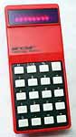
Friden EC-130, photographed at The National Museum of Computing, at Bletchley Park.
What did you think when you first saw the Friden EC-130 in 1964?
It was a fascinating, exciting, and very memorable experience to see this calculator for the first time; it was beautifully styled. In my opinion it
lost a bit in the translation to production dies. In external appearance, the EC-130 was a very good-looking, highly distinctive, stylish, rather low box with a gracefully-curved top cover over the electronics.
Do you remember any of the people at Friden who developed the Friden EC-130?
Friden had a wonderfully-capable engineer named Robert Ragen, one of the most brilliant people I have ever met, and a very pleasant, rather
self-effacing fellow at that. I don't know to what degree he was responsible for the remarkably innovative architecture of the EC-130, but I do know he had a significant hand in the design.
What makes the EC-130 tick?
When the EC-130 was designed, ICs were hopelessly expensive so the design used all discrete PNP germanium diodes and transistors. The circuits were primitive by today's standards but
they got the job done. To duplicate the internal logic of one of today's calculator chips with discrete components would give you a rather large box, too big for a desktop, which might draw a few hundred watts, and cost
probably $10,000.
Did Friden really use RPN before Hewlett-Packard?
The Friden EC-130 was the first calculator to use Reverse Polish Notation (RPN). It clearly preceded the HP 9100A, Hewlett-Packard's first calculator, which came
out in about 1968. The EC-130 no doubt served as the inspiration for the Hewlett-Packard desktop calculators. I'm almost sure that Friden also called it "RPN" at the time. So it wasn't HP who
first used RPN, and I don't think they claimed that they did. The EC-130 had a four-register visible stack functionally very close to that of the HP 48, for instance. A stack drop caused zeros to enter the
top. Not sure, but I think it might even have had a "Last x" register, but not displayed. It had an Enter key that worked probably exactly like that on the HP calculators.
Wasn't it outrageously expensive to display the results on a TV screen?
Well there wasn't much of a choice. Today's typical LED and LCD displays had not been invented. They could have used Nixie
tubes like the ANITA but that would have severely limited the number of digits displayed. So the characters were displayed on a 5-inch round, type 5DEP1 green-phosphor electrostatic-deflection CRT, with about 2 kV
accelerating voltage. In contrast, modern television and computer CRTs use magnetic deflection. The characters displayed on the screen were seven-segment, quite similar to those used in today's calculators.
The beam of the CRT was swept across the screen to write the strokes that made up the individual characters; it was a vector scan, not a raster scan. The deflection waveforms were wondrously complicated, and always the
same. The characters were slanted; the slant was created by just one resistor that cross-coupled the vertical deflection into the horizontal, without a buffer amplifier; it was a marvelously simple yet subtle circuit.
Individual digits were created by unblanking (turning on) the CRT beam at the appropriate times; the decoding matrix used a remarkably small number of diodes. (80 or so?) There was a decimal point visible in each register.
How did the EC-130 handle decimal points?
Logic for a floating decimal point, universal in contemporary calculators, was too elaborate to include in a discrete-component design. The EC-130 did have decimal points and
a decimal-point-entry key, but the display had a selectable fixed point, the same for all registers of the stack. The user had to decide how many decimal places s/he wanted to work with. There was a rotary switch with
an edge wheel knob projecting through a slot; there were about six choices available. I have seen two different sets of [numbers of places] in different machines. The internal logic permitted any number of places within
the limits of the machine; the switch was the limitation. Someone must have hacked a freely-selectable decimal selection at some time.
How many digits could the EC-130 display?
The machine had 13 digits, and by repositioning the decimal point, could provide all 26 digits of a product, as I recall. Overflow and/or truncation naturally occurred in
such cases. It could work as a purely fractional or purely integral machine.
Almost all calculators in 1964 were electro-mechanical. How did the new Friden EC-130 measure up?
Although a bit slower than today's $5 pocket calculator, it was a quantum leap over the mechanical machines of its
era. It did division with about 2 seconds required for an all-nines quotient. An all-nines multiplier was a bit faster.
The world's first electronic calculator, the Anita Mark IX was a full-keyboard machine with dozens of keys. What about the Friden EC-130 keyboard?
The EC-130 keyboard was serial-entry, so-called 10-key, much like
today's calculators. It had a unique mechanism, which was borderline practical as a design. Each key stem was part of a stamped piece of steel that included a "blade" with a rounded bottom edge. This
edge extended from front to back, and pressing a key moved it down against ramp-shaped recesses in a number of code bars (made of stamped phenolic laminate, I think). There were about 7 or 8 code bars; each had a small magnet
attached to it, and the magnet operated a reed switch. As I recall, there were no return springs on the code bars; they were actuated positively in both directions. The "touch" was quite acceptable despite the
oddity of the design. One code bar was actuated for any of the ten digits, and reset for other keys. The terms "common function" and "common digit" were frequently used by the tech. folk. There
was a small, fast electromagnet with an armature that locked the codebars in place (and locked down the keys as well; I have forgotten how) until a time-consuming operation such as mult. or div. was complete. It always was
pulsed, but most operations were quite fast, and it served as a keyclick noisemaker most of the time. It also could lock the keyboard when a malfunction happened; it wasn't rare for a defective machine to have its
multiplication key lock down and stay as soon as you pushed it.
How did the Friden EC-130 store numbers?
At the time it was designed, the EC-130 required too many digits of internal storage to permit use of discrete-component flip-flops for data; indeed, all of the early desktop calcs
faced the same constraint. Of course, this was the era before static RAM ICs. So Friden used a low-cost version of the wire (ultra)sonic delay line, a truly serial type of storage. These devices were used in
expensive systems for mass storage of binary data, with tight control over delay time and clock frequency. Apparently, the idea was to make the delay time some large multiple of the clock period, within a fraction of one
period. I'm not at all sure any more, but I seem to recall that the oscillator ran at around 650 KHz. The actual clock rate would have been 1/8 of that. The line itself was a subassembly on the bottom of the
calculator, with the wire in a large-radius (8" or so) flat helix/spiral of roughly a dozen turns or so. The wire itself was simply carefully-selected mild steel; no exotic alloy or such was needed. It was
supported by soft silicone rubber sheets with punched holes and loading slits. This whole affair sat in a shallow sheet aluminum tray-like chassis with a huge hole on the center. This type of delay line uses torsional
pulses that last a very few microseconds, if even that long. They are twists; their angular magnitude is probably substantially less than one degree of arc, and if they were even as small as seconds of arc, I'd not be
surprised. They also probably involve relatively high stress. It turns out that several thousand such pulses can be launched into a piece of wire, and they don't disperse much; they remain separate at the far
end. Launching such pulses is done with magnetostrictive tapes (pure nickel, probably) welded carefully to the exact end of the wire. My recollection is that each side of the wire used two tapes for engineering
reasons. These tapes were passed through the bobbins of two quite-tiny coils, and a permanent bias magnet was positioned close to the coils. The magnet's field made the tapes shorter by (perhaps) a few parts per
million than they would be without the field. Pulses to the coils cancelled the field for one tape, and doubled it for the other. In probably several hundred nanoseconds, the longitudinal stress pulses had travelled to
the end of the delay wire, where they gave it a sudden twist followed a microsecond or two later (roughly) by a relaxation to normal. The stress pulses in the tapes that travelled the other way would reflect from the ends of
the tapes; a few sheets of silicone rubber clamped onto the tapes (actually a support as well) absorbed them. At the other end of the delay wire, a transducer similar to the launch transducer converted the torque pulses to
longitudinal ones, and the inverse magnetostriction effect plus another permanent magnet developed a decent signal in another pair of tiny coils.
Did the EC-130 use binary code logic?
No! Amazingly, the internal representation of the digits was not binary, in fact wasn't really coded at all; it was radix-one! (Well, once on the wire, at
least...) Digits one through nine were represented really simply by consecutive pulses, with the pulse count equal to the digit being represented. A two was two pulses; a nine, nine pulses. Each digit was given
its own time slot in the total data time (1.9 ms, perhaps?). If there were no pulses occurring at a given time, then that digit was zero. I no longer recall how many internal 13-digit numbers were kept in the
calculator; there were the four stack registers, all displayed. I think there were two, possibly three others, not displayed. The numbers were written onto the delay line in a sequence with probably the
"hidden" registers first, then progressively up the stack.
What can you tell us about the electronic circuits in the EC-130?
As you know, the machine used no integrated circuits. Most transistors were 2N1305s, germanium PNP, in a TO-5 can. Faster ones were 2N2635s
(TO-18), I think; and the deflection output stages were 2N3866s, I think; I know they were a popular RF power transistor. Logic diodes (DTL) were 1N662s, fairly sure. The circuitry was highly optimized; each collector
load resistor and each of the base resistors was individually calculated; they were probably 1/2 watt Allen-Bradley carbon comps. (I don't think 1/4W; not sure.) Capacitors were chocolate-colored dipped mica,
mostly, also individually "calculated".
How were the individual components arranged?
There were seven circuit boards, approx. 12 inches by 5 inches; six were paired with spacers and (amazingly) lots of hand-soldered jumpers to join the two at the edges opposite
the connector edge. One connector served two boards in a pair. As to layout, they were mostly rather closely packed. I think the A through D counter/registers occupied either one board or one pair. The
boards were in a vertical plane, and plugged downward into edge connectors; no surprises.
How did they make the circuit boards?
The circuit boards were double-sided, with plated through-holes. The usual sequence was done: drill, then plate the holes. However, the pattern of traces was done by
reverse electroplating in a unique machine developed by the inventor Gilbert Marosi. The machine had a copper negative master wrapped around a drum and clamped. The drum was rotated in close registry with the drilled
and plated copy, while electrolyte was flushed though a very small gap between the master and the copy. The liquid went in clear, and came out blue. The copper was immediately extracted and the electrolyte reused.
The current must have been quite high, perhaps hundreds of amps. When it worked, it worked quite nicely. The remaining copper that had disconnected itself electrically was removed with a quick etch. However, there
was a nasty problem. The process of plating the through-holes created low anthill-like raised regions around the holes.
These would be of no consequence, but they shorted out the Marosi machine. The result was significant damage to the master; apparently it wasn't easy to stop the current before the damage was done. (Multi-hundred-ampere transistors were still in the future.) Manufacturing was, one would presume, in a major quandary. They apparently had to use the machine; setting up a conventional photoresist/etch line couldn't be done in a few days. They decided to follow the plating step with a surface grind of the unpatterned boards. I don't know about surface grinding copper, but they apparently almost knew how (if, indeed, anyone does). The consequences were horrible. The circuit boards would work fine until they were shipped to the branch offices, and even sometimes reach the customer's premises. Then the failures would begin. The surface grinding would damage the copper, breaking the plating inside the hole away from that on the surface.
What do you recall about servicing the EC-130 calculators?
It fell to me to be the East Coast "depot" service technician, or at least Northeast. We had commendably few actual part failures; about 98% of the
failures were due to the consequences of surface grinding. They were mechanical intermittents. We would get a set of boards in, plop them into a test machine (stock, but with extenders for all boards), have a look, and
start warping the boards. We saw some wondrously-peculiar symptoms; considering the architecture, they were more interesting than a more conventional architecture would have offered.
If we found more than, perhaps two definite symptoms, we opened up the pairs, and I painstakingly hand-soldered every through-hole on every board, with great attention to technique. I still recall a gold-plated transistor lead that was surrounded by a perfectly-good looking fillet of solder. Of course, the lead went through the board to a pad on the opposite side; that pad connected to some other circuits. The lead was not connected, however, to the pad on the component side, even though it was surrounded with a perfect-looking fillet. There must have been a very thin layer of rosin or other insulator on the lead, and the component-side pad had broken away completely from the plating in the hole. Solder continuity from bottom to top didn't help in this case.
What did you do after your work on the Friden EC-130?
My boss, a decent fellow, finally had me transferred to Friden R&D in Rochester, which is another interesting tale I may tell someday. Somewhat sad; lost
opportunity, but also mismanagement. R&D ended back in 1966, I think with early corporate downsizing/R&D cutbacks. It hit me early! Singer had bought Friden about the time I first went to work for them, and
progressively destroyed a very good company.
See also the page on the Friden EC-130 and EC-132 on this site.
Calculator Articles
Vintage Calculators
Text & photographs copyright, except where stated otherwise, © Nigel Tout 2000-2026.